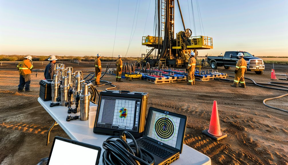
You map subsurface targets, set anti-collision envelopes, and design a trajectory with dogleg and tortuosity limits, then select a BHA—motor or RSS—with MWD/LWD and the right bit. You kick off, hold angle, and steer using surveys, real-time telemetry, and geosteering while managing hydraulics, torque/drag, and vibration. You condition the hole, ream as needed, and validate uncertainty models before landing the lateral and tying in. But the workflow only works if you…
Mapping the Wellpath: Targets, Constraints, and Anti-Collision
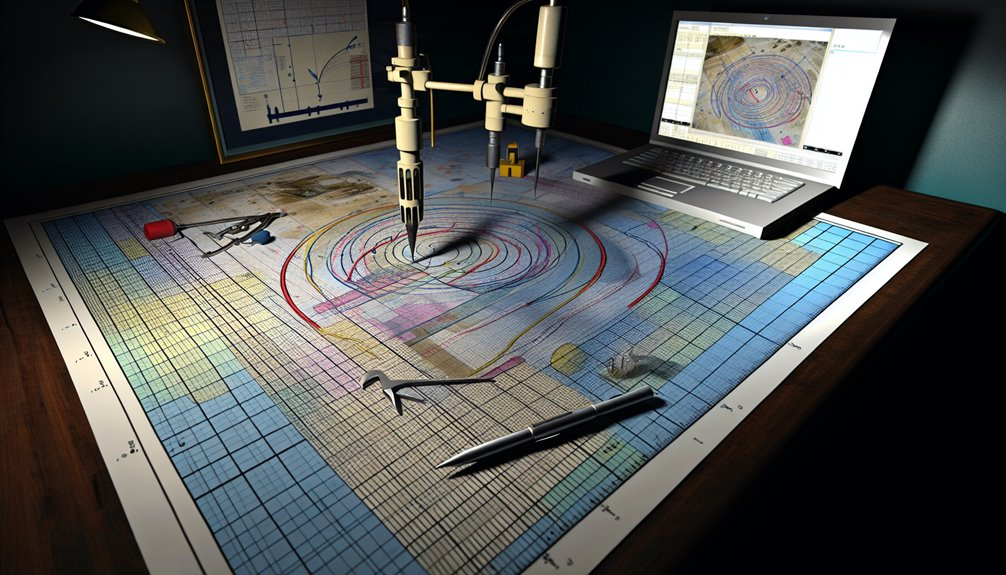
Before you pick up a bit, define the 3D wellpath by quantifying targets, constraints, and collision risk.
You start by converting reservoir targets into measurable windows: TVD ranges, lateral extents, and azimuth corridors tied to structure maps and uncertainty envelopes.
Set regulatory setbacks as hard boundaries, integrating lease lines, right-of-way buffers, and environmental exclusions.
Build a probabilistic anti-collision model using ISCWSA error sets, survey tool performance, and planned separation factors.
You’ll compute ellipses of uncertainty, run proximity scans against nearby wells, and enforce a minimum separation rule with alert thresholds.
Validate casing shoe depths, build-rate capabilities, and torque-drag limits against BHA and drillstring specs.
Align mud weights and expected pressures to maintain borehole stability while preserving geosteering latitude around key pay.
Building the Plan: Trajectory Design and Toolface Strategy
With targets, constraints, and collision envelopes quantified, you convert that framework into a drillable trajectory and toolface program. You select section geometries—build, hold, turn—using tortuosity limits, BHA dogleg capability, and bit aggressivity. You model planned dogleg severity versus friction coefficients to protect torque-and-drag margins and casing wear. You set motor yield and expected slide/rotate ratios to achieve azimuth/inclination rates while preserving ROP.
You anchor toolface strategy on precise bitface calibration and disciplined sensor integration. You align surface references with downhole magnetics and gravity vectors, apply declination and sag corrections, and validate toolface repeatability with offset statistics. You define survey spacing and decision thresholds to bound cumulative TVD/azimuth error. You precompute slide sheets, micro-adjustments, and contingency turn plans, ensuring the crew executes consistently under real-time variance.
Downhole Toolkit: Mud Motors, RSS, MWD/LWD, and Bits
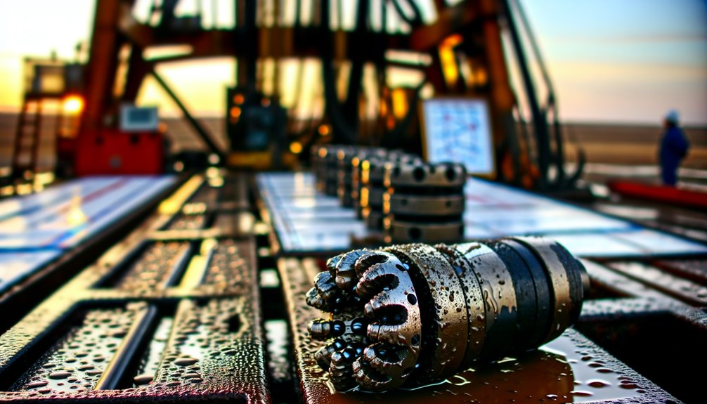
Calibrate your downhole toolkit to the trajectory and formation mechanics, not habit. You’ll match steerability, rate of penetration, and borehole quality to rock strength, abrasivity, and pore pressure.
For build/turn in mixed lithology, choose a positive-displacement mud motor with adjustable bend; target 1.5–3.0°/100 ft dogleg while managing torque and differential pressure. For smooth curves and extended laterals, deploy rotary steerable systems; use closed-loop downlinking and continuous rotation to cut tortuosity, reduce stick-slip, and protect casing running.
Pair measurement while drilling and LWD sensors to decision points: high-frequency surveys, azimuthal gamma, density/neutron, resistivity imaging, and shock/vibe. Optimize bit selection by UCS and grain size: PDC with depth-of-cut control for shales; TCI roller cone for interbedded/calcite streaks. Validate with real-time vibration/ROP models and post-run dulls.
Spudding and Pilot Hole: Kicking Off and Holding Angle
Kick off clean and controlled by tying surface parameters to subsurface mechanics. You spud with intent: confirm surface alignment with a total station, set the starter casing angle within ±0.25°, and verify mast plumb to ±0.05°. Lock in crew coordination through a roles matrix—driller manages weight-on-bit ramps, directional hand tunes toolface, mud engineer guards rheology for cuttings lift. Execute spud monitoring: record RPM, torque, WOB, flow, and standpipe pressure at 10-second intervals; trend mechanical specific energy to detect formation stiffness changes.
Build angle deliberately. Use short sliding increments to achieve the planned dogleg, then rotate to hold. Control vibration by capping surface RPM and smoothing WOB steps. Maintain gauge with consistent ROP and clean hole—sweep volumes sized to interval length and annular velocity.
Steering With Data: Surveys, Real-Time Telemetry, and Geosteering
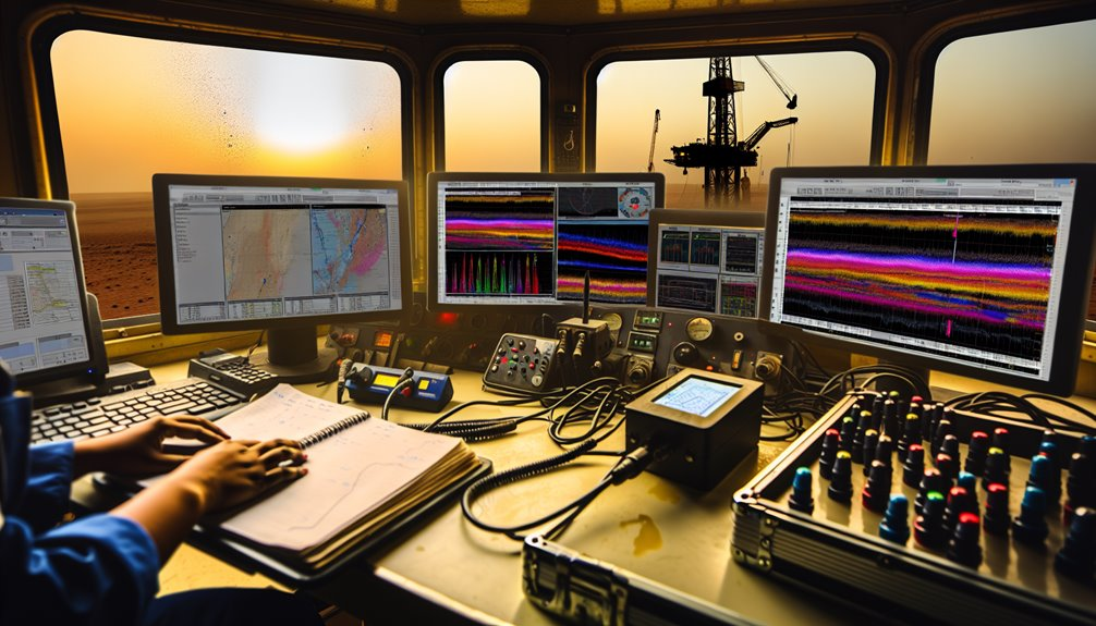
Although the bit’s downhole behavior is invisible, you steer precisely by turning measurements into actions. You acquire surveys on schedule, validate inclination/azimuth against offsets, and apply real time calibration to correct toolface bias, sag, and magnetics. You fuse MWD/LWD gamma, resistivity, and density with survey quality indicators to quantify uncertainty and update the wellpath.
You close the loop with telemetry: high-frequency downlinking uplinks toolface, shock flags, and gamma trends so you adjust motor yield or rotary walk. You run geosteering in probabilistic models, assimilating cuttings lag, gamma markers, and bed-dip to refine reservoir interpretation. When the boundary moves, you correct slide/rotate sequences and micro-adjust DLS to stay in zone, maximizing exposure while honoring anti-collision, tortuosity, and lease-line constraints.
Managing Mechanics: Torque and Drag, Hydraulics, and Vibration Control
While geosteering sets the target, you hold the well on plan by managing mechanical limits in real time—quantifying torque/drag, optimizing hydraulics, and suppressing vibration.
You track surface torque, differential torque, and hookload trends against modeled friction factors. Apply torque management by adjusting WOB, RPM, and ROP to keep torque below tool limits and avoid stick-slip onset.
Use hydraulics models to hit bit HSI and nozzle DP targets, maintain annular velocity above cuttings slip, and manage ECD to protect the formation.
For vibration mitigation, monitor MWD shock, axial/ lateral acceleration, and torsional spectra; tune RPM-WOB windows, rotary vs. slide ratios, and downhole dampers.
Validate changes with step tests, comparing before-after torque, MSE, and downhole shocks to lock in stable, efficient parameters.
Hole Conditioning: Reaming, Circulation, and Stability Checks

Planning each interval’s hole conditioning prevents hidden risk from accumulating before trips or casing.
You set objectives: confirm gauge, make certain equivalent circulating density (ECD) margin, and verify wellbore stability.
Match ream size to bit diameter, stabilizer OD, and expected dogleg to smooth micro-ledges without overcutting.
Execute wiper trips with measured ROP, then backream at controlled RPM and WOB, tracking hookload deltas and torque decay to confirm clean-up.
Circulate bottoms-up with high-velocity sweeps sized by annular volume; tune rheology to suspend solids at zero pump, not just at rate.
Use cuttings control indicators—shale density, shape, and lagged volume—to adjust flow rate and sweep frequency.
Monitor standpipe trends, ECD vs. pore/frac windows, and cavings character.
If cavings persist, increase inhibition, reduce annular friction, and extend circulation.
Landing, Drilling the Lateral, and Tying In to Production Systems
With the hole conditioned and hydraulics verified, you set the landing targets and execute the build to hold angle within ±0.2° and azimuth within ±1°. You apply landing procedures with continuous MWD/LWD gamma, resistivity, and density-neutron to confirm top of reservoir; adjust toolface and build rate to keep TVD error <1 m. You validate torque/drag trends and ECD margin <0.3 ppg to protect the shoe.
Kick off the lateral with RSS or high-build motors, hold inclination within ±0.1° and tortuosity <1.5°/100 ft. Optimize ROP using WOB/rotary RPM response curves, vibration limits, and bit dull data. Manage cuttings with SWAB/AV checks and flowback samples.
At TD, run production casing, cement to plan, install sleeves/packers, pressure-test, and complete the production tie in via flowline hookup, metering, and SCADA integration.
Conclusion
That’s the heart of how we do it at Boring Bros.: a disciplined workflow that turns subsurface intent into a high‑quality wellbore. I map the targets, enforce anti‑collision and uncertainty limits, and design trajectories with dogleg and tortuosity controls. I pick BHAs, bits, and MWD/RSS to match the rock, then steer with careful survey QC, real‑time telemetry, and geosteering. We manage torque, drag, hydraulics, and vibration, condition the hole, and land the lateral on spec—so casing, cement, and tie‑in go smoothly with minimized risk and maximum production deliverability. If you want to learn more or talk about a project, visit boringbro.com or give us a call at (954) 639‑6167 — I’d love to hear from you.

