Before you plan any residential bore, you’ll verify utility locates, select the right GPR antenna for target depth, and set up safe access with proper PPE and traffic control. You’ll clear the surface, mark APWA colors, and run calibrated test lines to confirm time-zero and encoder accuracy. Then you’ll grid the site, assign confidence levels to anomalies, and decide when to pothole or cross-check with EM. Miss a step, and the risk rises fast.
Understanding GPR and Its Role in Residential Boring
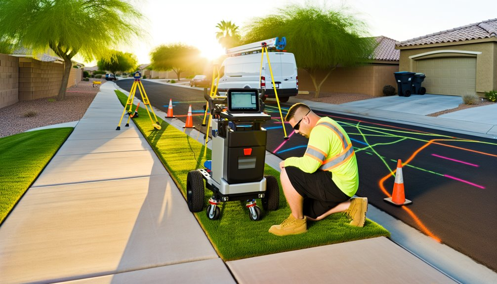
Before you set a drill, ground penetrating radar (GPR) gives you a non-invasive way to locate subsurface utilities, voids, and structural elements that could compromise a residential boring operation.
You apply GPR basics by selecting an antenna frequency that balances depth and resolution—low for deeper targets, high for fine detail.
Through subsurface imaging, you interpret hyperbolic reflections, layer interfaces, and signal attenuation to flag hazards, confirm clear zones, and set safe offsets.
You calibrate to surface conditions, verify time-zero, and maintain consistent transect spacing for repeatable results.
You document findings with grids, depth estimates, and confidence levels, aligning your methods with applicable standards.
Using GPR this way, you protect people, property, and schedules—and you contribute to a culture of responsible practice.
Coordinating GPR With One-Call Utility Locates
Even after you call 811 and utilities mark their facilities, you still coordinate GPR to validate, refine, and de-risk the bore plan.
You treat one-call marks as preliminary, then overlay GPR results to confirm depth, alignment, and unmarked laterals.
Document variances with georeferenced sketches and photographs, and reconcile conflicts with utility coordination before finalizing drill paths.
Sequence the steps: open ticket, receive clear/mark, perform GPR within ticket validity, and update the plan if relocates are required.
Use technician scheduling to guarantee certified operators and calibrated equipment are onsite when locators’ marks are fresh.
Communicate electromagnetic frequencies, expected target types, and tolerance zones, and require utility reps to review anomalies.
Close the loop with a signed conflict matrix, revised bore profiles, and archived records.
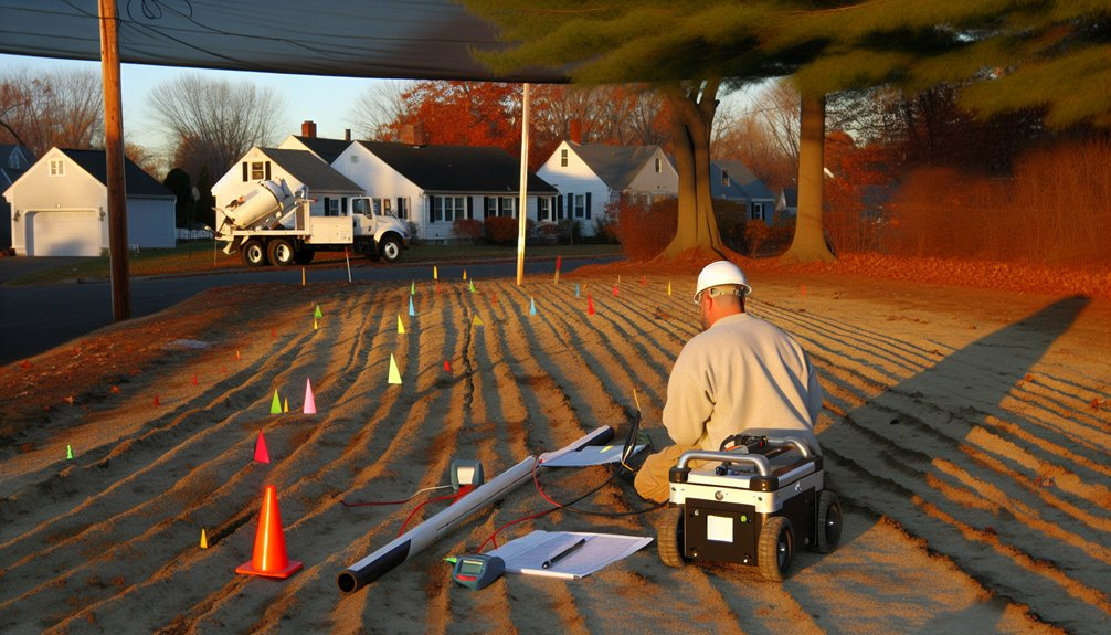
Site Assessment and Surface Preparation

Although one-call and GPR coordination set the baseline, you still start the site assessment by delineating the survey limits, access routes, and safe standoff from traffic, structures, and overhead hazards per MUTCD and OSHA 1926.
Verify grades, pavement types, and soil conditions that influence antenna coupling and data quality. Plan traffic control with certified setups, sight-distance checks, and flagging where required.
Confirm equipment clearances under power lines and tree canopies; schedule vegetation removal only where it improves coupling and visibility. Remove metallic debris, loose gravel, and saturated mud that mask returns.
Document drainage paths to prevent slip hazards and instrument exposure. Establish exclusion zones for residents and pets. Calibrate wheel encoders and time-zero on a clean test patch before production scanning.
Marking Conventions and Color Codes for Subsurface Features
Because utility misidentification drives most strike incidents, you’ll apply standardized markings that match APWA color codes and MUTCD/OSHA legibility requirements. Use white for proposed work, red for electric, yellow for gas, orange for communications, blue for potable water, purple for reclaimed, green for sewer/drain, pink for survey control. Maintain 2-inch line width, high-contrast paint or flags, and weatherproof notes.
Create a site color legend at access points so everyone reads marks the same way. Pair painted lines with feature tagging: abbreviations, depths, method (GPR), confidence level, and date/initials (e.g., RED ELEC 0.8 m GPR C2 2025-08 JD). Arrowheads show utility direction; dashed lines indicate inferred routes; X marks conflicts. Re-mark after precipitation, traffic, or layout changes. Photograph and log all markings for traceability.
Equipment Selection: Antenna Frequencies and System Options
Which GPR system fits your residential boring scope hinges on target depth, size, and soil conditions, so match antenna frequency and platform accordingly. Select high frequency antennas (900–1600 MHz) for shallow, small targets like service laterals; choose midband (400–800 MHz) for mixed utilities; use low frequency (200–400 MHz) for deeper mains where resolution can be lower. Prioritize systems with shielded antennas for tight yards and EM-noise areas. In clay-rich soils, expect reduced penetration; compensate with lower frequencies and tighter line spacing. For large frontage or roadway projects, vehicle mounted systems improve coverage and lane safety; for backyards, carts or sleds reduce access risk. Verify local right-of-way rules, traffic control standards, and locator coordination to keep your crew aligned and code-compliant.
- Depth vs. resolution trade-offs by MHz band
- Soil conductivity impacts on penetration
- Platform choice: handheld, cart, vehicle mounted systems
- Shielding and interference considerations
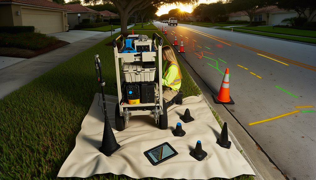
Calibration, Test Scans, and Quality Control Checks
Even before you mark a grid, establish calibration, run test lines, and document QC steps that meet your company SOPs and local standards.
Verify wheel encoder, time-zero, and dielectric settings with a certified calibration block or known target.
Perform signal validation by scanning a mapped utility to confirm depth scale and polarity.
Execute orthogonal test lines to evaluate coupling and repeatability.
Apply noise reduction: check for external RF sources, set appropriate stacking, and confirm shield integrity.
Lock project-specific parameters, then record screenshots and metadata for traceability.
During production, implement interval-based QC: re-run a control line, compare hyperbola fits, and verify drift hasn’t occurred.
Use peer review to confirm interpretations.
If discrepancies arise, pause, re-calibrate, update logs, and communicate changes to the team.
Soil, Moisture, and Depth Limitations You Must Consider
With calibration and QC controls in place, you now must account for how subsurface conditions govern GPR performance. Electrical conductivity and dielectric contrasts dictate penetration and target clarity. High clay content and saline soils boost attenuation; dry, resistive sands extend depth. Moisture gradients create velocity drift, multiple reflections, and phase reversals. Match antenna frequency to expected depth and resolution, and document site-specific limits to stay code-compliant and aligned as a team.
1) Assess soil classification: log clay content, silt, and organics; anticipate loss mechanisms and scattering.
2) Map moisture gradients by grid: correlate rainfall, irrigation, and drainage to time-varying response.
3) Select frequency: 250–400 MHz for utilities at moderate depths; 600–900 MHz for shallow detail.
4) Set realistic depth-of-detection: validate with test targets; record maximum reliable depth, not theoretical.
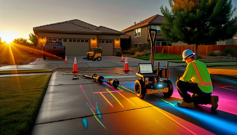
Safe Work Practices, PPE, and Field Communication
Before you energize a GPR cart or mark a bore path, establish a job hazard analysis and brief the crew on task steps, roles, and stop‑work criteria. Verify utility locates, weather, and site access. Set up traffic control per MUTCD and local ordinance; post spotters and delineate exclusion zones.
Wear ANSI Z89.1 hard hats, high‑vis Class 2 or 3 vests, cut‑resistant gloves, eye protection, and steel‑toe EH boots. Use hearing protection near generators. Ground and inspect cords; manage trip hazards. Maintain antenna standoffs and follow manufacturer RF exposure guidance.
Adopt fatigue management: rotate scanning, hydrate, schedule micro‑breaks, and pause if concentration drops. Use plain‑language radio calls, hand signals, and a single point of command. Document changes and confirm read‑backs.
Data Interpretation, Confidence Levels, and Ground Truthing
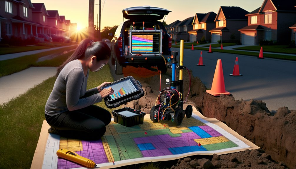
You’ve set safe work practices and communications; now apply the same discipline to interpreting GPR data and assigning confidence levels. Read traces methodically, verify hyperbola geometry, and quantify uncertainty. You’re not alone—your team’s consistency builds trust and reduces risk before any bore.
- Establish velocity models using known depths; adjust until layer correlation stabilizes. Note soil moisture changes that shift dielectric values.
- Classify targets by signature quality: amplitude, continuity, and hyperbola fit. Flag signal ambiguity and assign conservative confidence tiers.
- Cross-validate with complementary methods (EM, utility locates, potholing) to ground-truth high‑risk anomalies. Escalate when datasets diverge.
- Set acceptance thresholds: minimum passes, orthogonal lines, and tolerance for depth deviation. If thresholds aren’t met, rescan or re‑scope.
Always privilege safety over schedule when confidence drops.
Documentation, Mapping Deliverables, and Record Keeping
Although field decisions happen fast, your documentation must be deliberate, traceable, and audit‑ready.
Capture chain‑of‑custody for raw GPR files, calibration settings, antenna IDs, GPS accuracy, and time stamps.
Tie every scan to a bore plan ID and site control.
Use consistent symbology for utilities, voids, and no‑go zones.
Issue mapping deliverables as georeferenced PDFs and GIS layers with metadata: projection, datum, survey method, confidence class, and locator initials.
Include cross‑sections, depth estimates, and offset tolerances.
Lock deliverables using version control and change logs to show what changed and why.
Apply a record retention schedule aligned with client contracts and local code.
Secure storage with checksums, access roles, and backups.
After ground truthing, reconcile variances, update maps, and close findings with sign‑off.
Conclusion
At Boring Bros, we take pride in planning every job with care — pairing one-call locates with calibrated GPR, validating time‑zero, running orthogonal lines, and marking per APWA color codes. We pick the right antennas for depth and soil conditions, enforce PPE, traffic control, and clear communication, and assign confidence levels so low‑certainty anomalies get the right follow‑up with EM or potholing. We respect depth and moisture limits, maintain chain‑of‑custody, archive georeferenced deliverables, and document our decisions—because that’s how we keep people, utilities, and your schedule protected. If you want to learn more about our approach or talk through a project, please visit boringbro.com or give us a call at (954) 639‑6167 — we’d love to help.