
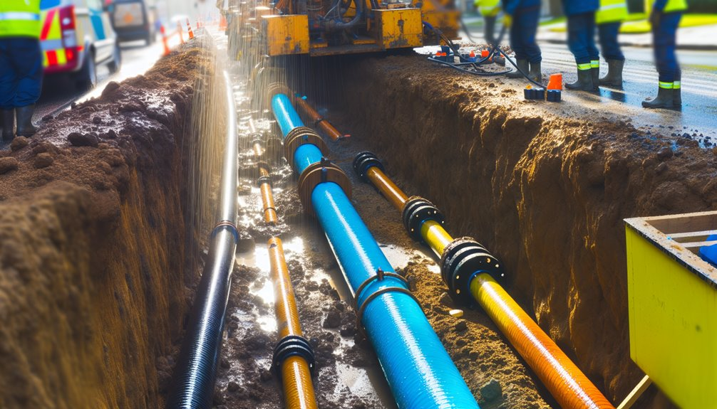
You’re considering a shared HDD bore for water, gas, and electric to cut surface impacts and right‑of‑way costs, but you can’t shortcut design rigor. You’ll need clearances that meet code, cathodic and stray‑current control, thermal modeling for cables and gas, and materials that won’t interact. Plan geotech, pilot-path tolerance, ream strategy, and pull sequence. Define isolation, test protocols, and access points. Permits and acceptance criteria matter—miss one, and the whole corridor is at risk.
When a Shared Bore Makes Sense
Although separate alignments are often safer, a shared bore makes sense when you can demonstrably meet utility separation standards, maintainable access, and lifecycle reliability at lower total risk and cost than parallel bores. You validate minimum clearances for heat, stray current, and pressure zones, and prove you can isolate, inspect, and replace each line without disrupting others. You quantify constructability and O&M risk, then compare it to right-of-way conflicts and surface impacts.
Use route optimization to minimize crossings, spans, and bends, improving pull forces and reducing strike potential. Standardize spacers, markers, and tracer systems. Define shared liability with clear interface points, responsibilities, and contingency funding. Verify soil stability, buoyancy control, and cathodic compatibility. If your risk register trends lower than dual bores, you’ve got the right case.
Regulatory Frameworks and Permitting Requirements
Your shared-bore case only holds up if it threads through the regulatory lattice—federal pipeline safety rules, electrical codes, trenchless construction standards, and local right‑of‑way ordinances—without creating new risk. You’ll harmonize permits across authorities having jurisdiction, demonstrate zoning compliance, and document environmental assessments that address cumulative impacts. Anchor your submittals to named standards (e.g., 49 CFR Parts 192/195, NFPA 70, ASCE/NASTT trenchless guidance) and cite your operator qualifications and inspection plans. Show stakeholders you’re not cutting corners; you’re building trust.
- Map authorities, permits, and review clocks; pre‑meet to surface deal‑breakers.
- Submit an integrated risk register with mitigations tied to enforceable codes.
- Prove constructability via stamped HDD plans, QA/QC, and contingency routing.
- Commit to post‑construction compliance: as‑builts, pressure/electrical tests, and monitoring.
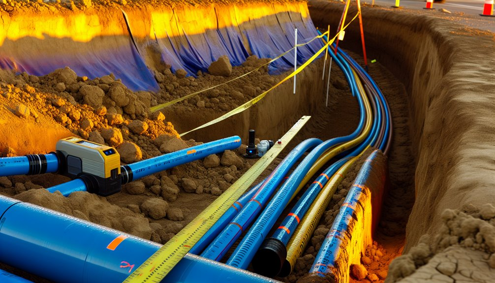
Minimum Separation and Clearance Standards
Even when you co-locate utilities in one bore, minimum separations aren’t negotiable—they’re codified constraints that drive your profile, product pipe order, and spacers.
You’ll hold to utility-to-utility clearances (often 12–24 inches radial) and utility-to-structure offsets per standards and manufacturer listings. Prioritize gas isolation from electric, maintain potable water above potential contaminants, and respect thermal envelopes around primary conductors. Document your basis of design: codes, authority amendments, and utility-owner specs to demonstrate regulatory compliance.
Set spacer intervals to prevent ovalization and contact under buoyancy or thermal cycling. Validate bend radii and sags so clearances persist under operating loads. Use soil testing only to confirm load-bearing and settlement assumptions that protect clearances.
Record as-builts with stationing and offsets, and commit to re-verification during tie-ins.
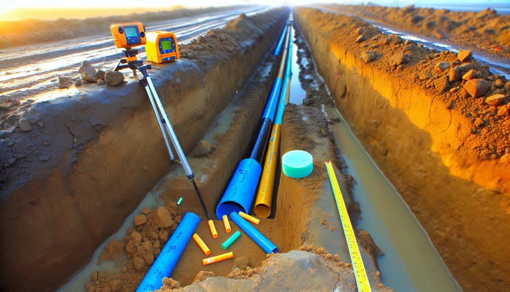
Ground Conditions and Geotechnical Investigations
Clearances only persist if the ground supports them, so you characterize the subsurface with a fit-for-purpose geotechnical program before fixing the bore path. You validate assumptions with soil sampling, groundwater mapping, and lab classification to ASTM and EN standards. You log stratigraphy, lenses, and weathering so multi-utility conduits don’t migrate, float, or pinch.
1) Define data needs: boring depths exceed invert by 1–2 diameters; sample disturbed/undisturbed; test shear strength, density, abrasivity, corrosion.
2) Map hydrogeology: seasonal highs, gradients, recharge; quantify inflow risk, piping, and uplift.
3) Assess constructability: HDD steering in gravels, collapse in silts, swelling clays; specify drilling fluid windows and annular pressure limits.
4) Design for performance: set cover, bedding, restraint, and backfill gradations; set monitoring triggers.
Document uncertainties, assign risk owners, and iterate alignment early, together.
Thermal Management for Electric and Gas Lines

Often overlooked until late design, thermal management governs whether co-located electric and gas lines meet ampacity, pressure containment, and longevity targets. You’ll model soil thermal resistivity (per IEEE 835/IEC 60287) and gas line heat exchange to set trench/bore spacing, backfill selection, and continuous rating.
Verify composite thermal resistivity of grout, flowable fill, or sand; avoid hotspots near HDD annuli and changes in condition. Use thermal blankets or radiant barriers to decouple heat from high-load feeders, especially at crossings and joint bays.
Validate ampacity with cyclic loading and emergency ratings; check gas temperature rise against pipe MAOP and EN/ASME limits. Instrument critical segments with distributed temperature sensing.
Document as-built thermal interfaces, and require maintenance protocols that preserve backfill integrity, barrier continuity, and airflow around vault terminations.
Corrosion Control and Cathodic Protection Strategies
Thermal interfaces you just defined also influence electrochemical behavior, so treat corrosion control as a co-equal design constraint from routing through commissioning. You’ll verify coating integrity, isolate dissimilar metals electrically, and manage stray current from transit, DC traction, and utility faults. Specify test stations and bonds that meet NACE SP0169/AMPP 21610, ASTM G8, and local permitting.
- Perform close-interval and DCVG surveys to baseline coating integrity before energizing impressed current systems.
- Model current attenuation along the corridor; select anode configurations (distributed vs. deep well) to achieve criteria without overprotection.
- Design robust isolation joints and decouplers; validate that fault and lightning duties don’t compromise cathodic separation.
- Implement monitoring: coupons, reference electrodes, and remote telemetry; alarm on depolarization trends.
Commission with interference testing, document interference bonds, and set rectifier setpoints that respect all owners.
Material Selection and Compatible Pipe Systems
Although one bore path tempts you to standardize, select materials by load cases, environment, and regulatory duty, then prove compatibility at interfaces.
Match pressure class, temperature range, and fatigue resistance to each utility’s duty cycle.
For gas, specify PE 4710 or PA‑12 where codes allow; for water, use AWWA-compliant HDPE or ductile iron with lined interiors; for electric, use Polyethylene conduits rated to UL/NEMA, with UV and pulling approvals.
Deploy Stainless steel only where chloride stress cracking and stray current risks are mitigated per NACE guidance.
Validate dielectric separation between dissimilar metals, fire rating, and grounding continuity.
Confirm gasket elastomers, thread compounds, and couplings meet NSF/ASTM/API listings.
Document jointing procedures, tracer wire schemes, and spacers ensuring maintained clearances.
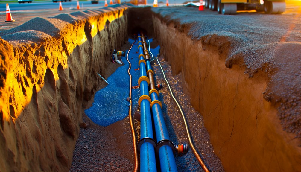
HDD Design, Pilot Path, and Reaming Considerations
Before you stack utilities in one bore, lock down an HDD design that controls curvature, annular pressure, and separation. You’ll validate bore curvature limits to keep cables within tensile and bend radii while preserving clearance to adjacent pipes.
Plan the pilot path with entry/exit geometry that maintains drill-string stability, minimizes inadvertent returns, and aligns with ASTM F1962 and ASCE guidelines. Size ream passes to control cuttings transport and torque; verify fluid lubrication, gel strength, and return rates to prevent frac-outs and settlement.
- Model bore curvature, steering response, and pullback loads with conservative safety factors.
- Set minimum separations, cover, and annular pressure windows by soil class.
- Specify fluid lubrication programs and additives for each ream.
- Instrument the pilot and ream with tracking, pressure, and returns monitoring to enforce compliance.
Installation Sequencing and Stakeholder Coordination

Even with a robust HDD design, you still need a disciplined installation sequence and tight stakeholder coordination to keep multi-utility bores compliant and low risk. You’ll codify phasing, hold points, and acceptance criteria before the first stick goes in.
Use phased scheduling to stage conduits by hazard class—gravity sewer or water first, then telecom, then gas, then electric—maintaining clearance envelopes, thermal separation, and cathodic protection rules. Verify pullback order, lubricant compatibility, and seal-offs per applicable standards.
Build stakeholder mapping that names owners, AHJs, one-call, traffic control, and emergency services, with RACI assignments and escalation paths. Lock submittals, MOPs, and ITPs; run readiness reviews; and document as-built variances immediately.
You’ll sequence testing and energization gates so each utility passes pressure, continuity, and isolation checks before the next mobilizes.
Access Points, Monitoring, and Maintenance Planning
From the outset, design access points that let you inspect, isolate, and service each utility without compromising the others. Standardize vault spacing, clearances, and valve/sectionalizer orientation per AWWA, NFPA 54, and NESC. Specify labeled conduits, keyed locks, and gas-rated ventilation. Integrate sensors for cathodic protection, leak detection, pressure, and load to enable Remote Diagnostics and trend baselines. Build maintainability into Access Scheduling so crews coordinate outages, permits, and confined-space protocols without schedule collisions.
- Define inspection intervals tied to risk and consequence; document triggers for unscheduled entry.
- Map isolation boundaries; validate fail-safe states and backfeed prevention before energization.
- Implement condition-based maintenance using thresholds and alerts, not calendar alone.
- Drill on joint response: unify call trees, data logs, and post-incident reviews to strengthen shared accountability.
Conclusion
As the owner of Boring Bros., I’ve seen firsthand how combining water, gas, and electric in a single bore path can work—provided it’s done with discipline, clear standards, and the right engineering controls. We always start by validating codes and permits, proving geotechnical assumptions, and locking in minimum clearances. We engineer for thermal, pressure, and electrical separation, choose compatible materials, and mitigate stray current. Our HDD design, sequencing, and testing follow strict acceptance criteria, and we provide independent access, monitoring, and isolation so each utility stays inspectable, repairable, and replaceable—protecting safety, reliability, and lifecycle cost. If you’d like to learn more or discuss a project, please visit boringbro.com or give us a call at (954) 639-6167 — we’d love to help.